Project Tasks and Requirements
Tasks
Design and build a moving target control and automatic tracking system. The system includes a red spot position control system to simulate the moving target and a green spot position control system to indicate automatic tracking. The system structure and placement are shown in Figure 1(a). Two laser pens are fixed on their respective independent two-dimensional electric control pan-tilt platforms.
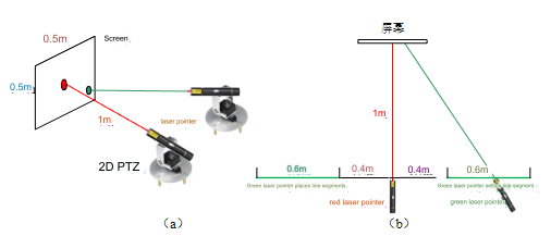
Figure 1 Moving Target Control and Automatic Tracking System Structure and Placement Diagram
The red laser pen's spot simulates the moving target, which falls on a white screen 1 meter in front, with a spot diameter ≤ 1 cm. The red spot position control system allows the spot to move anywhere within the screen range.
The green laser pen's spot is controlled by the green spot position system to automatically track the red spot on the screen, indicating the effect of automatic tracking, with a spot diameter ≤ 1 cm. The green laser pen placement line is shown in Figure 1(b), which is parallel to the screen and located on both sides of the red laser pen, with a distance greater than 0.4m and less than 1m from the red laser pen. The green laser pen can be placed arbitrarily on the two placement lines.
The screen is white, with an effective area greater than 0.6 x 0.6 m². A square with a side length of 0.5m is drawn in the center of the screen with a pencil to mark the screen's edges; the center of the drawn square is the origin, and the origin position is marked with a pencil, with a pencil trace width ≤ 1mm. The red and green spot position control systems must be independent and cannot communicate in any way; the spot diameter is less than 1 cm; there are no electronic components on the screen; the control system cannot use desktop computers or laptops.
Requirements
Basic Requirements
Set a reset function for the moving target position. When this function is executed, the red spot can return from any position on the screen to the origin. The error between the center of the spot and the origin ≤ 2 cm.
Activate the moving target control system. The red spot can move clockwise around the four edges of the screen within 30 seconds, with the distance between the center of the spot and the edge ≤ 2 cm.
Use about 1.8 cm wide black electrician tape to stick a rectangle along the four sides of an A4 paper, forming an A4 target paper. Stick this A4 target paper at a designated position on the screen. Activate the moving target control system, and the red spot can move clockwise along the tape within 30 seconds.
Stick the above A4 target paper at any rotation angle on the screen at any position. Activate the moving target control system, with the same requirements as 3.
Advanced Requirements
Reset the moving target position, one-key start the automatic tracking system, control the green spot to track the red spot within 2 seconds, and issue continuous sound and light prompts upon successful tracking. The distance between the centers of the two spots should be ≤ 3 cm.
Repeat the actions of the basic requirements 3 ~ 4 for the moving target. The green laser pen emitter can be placed at any position on its placement line, simultaneously activate the moving target and automatic tracking system, and the green spot can automatically track the red spot. After 2 seconds of system startup, it should track successfully and issue continuous sound and light prompts.
Both the moving target control system and the automatic tracking system need to set a pause key. When the pause key is pressed simultaneously, the red and green spots should immediately brake to measure the distance between the centers of the two spots.
Implementation Plan
In response to the technical parameter requirements of the selected topic, this design uses the ESP32-S3 microcontroller as the control core of the entire system, selecting hardware devices such as Orange Pi, NVIDIA Jetson, brushless DC motors, two-dimensional pan-tilt, and RGB camera, and combining programming in C++ and python3.6, which can better achieve the design requirements. After testing, regardless of the position of the A4 target paper on the screen, the designed system can effectively recognize the target paper, and the red spot controlled by the pan-tilt can complete a clockwise movement on the target paper within 30 seconds. In addition, by adopting image processing algorithms such as color space conversion, binarization processing, and Gaussian filtering, the designed system can better achieve recognition and motion tracking of red and green spots, and during the tracking process, the center distance of different spots can be kept within 3 cm at all times.
Scheme Demonstration
This system mainly demonstrates the selection of motors, image processing modules, and main control chip selection, with other peripheral supporting hardware being conventional design.
Motor Selection
Option 1: Use servos as the main operating structure components of the pan-tilt
Servos are motors with position feedback that can accurately control the motor angle, usually consisting of a DC motor, position sensor, and control circuit. However, during servo control, the operating speed is relatively slow, and stability and accuracy are relatively poor. According to the technical indicators of the selected topic and the tentative tests of our team members, using servos cannot meet the high-precision real-time position control requirements of laser points during operation.
Option 2: Use stepper motors as the main operating structure components of the pan-tilt
Stepper motors are electrical pulse input motors that can control the rotation angle and speed by changing the number of pulses, with high operating precision. However, using only stepper motors cannot achieve stable closed-loop control of laser points, and it is necessary to combine other sensors for testing, which can easily lead to significant cumulative errors. In addition, stepper motors have some disadvantages in terms of motion rate, dynamic response, step loss problems, and electromagnetic interference.
Option 3: Use brushless DC motors as the main operating structure components of the pan-tilt
Brushless DC motors can control the rotor position of the motor through an electronic commutator. The permanent magnet on the rotor of the brushless motor and the coils on the stator are alternately excited through the electronic commutator to achieve the rotation of the motor. Compared with the previous two options, brushless DC motors have the characteristics of high efficiency, high torque, and high speed. Through control with PWM and PID algorithms, they can better meet the requirements of the selected topic for fast and accurate movement and tracking of laser points. Therefore, this design selects brushless DC motors as the main operating structure components of the two-dimensional pan-tilt.
Image Processing Module
Option 1: Use the built-in processing module of OpenMV
OpenMV is a low-power image processing module based on the Python programming language, equipped with an ARMCortex-M7 processor, with real-time image processing functions such as image denoising, color recognition, QR code and barcode recognition, etc. However, the preliminary test results of our team members on OpenMV show that the camera performance of this image processing module is average, and it is not sensitive enough to changes in the ambient scene light source. During the recognition of lasers, it is easily affected by the power of the laser, leading to a decrease in recognition accuracy.
Option 2: Use the built-in processing module of K210
K210 is a system-on-chip based on the RISC-V architecture, with dual-core 64-bit RISC-V processors, image processing units, and artificial intelligence support functions, which is a mainstream image processing module on the market. However, the built-in camera performance of K210 is also not outstanding, and its flash is small, sometimes causing stuttering or even crashing when flashing large firmware, and the connection communication between the supporting development environment and the lower machine is not stable.
Option 3: Use Orange Pi/NVIDIA Jetson as the processor, and connect a high-definition camera module
Compared with the common camera processing modules on the market such as OpenMV and K210, the external high-definition RGB camera module has higher image resolution and can be better used for image recognition tasks. In order for the designed system to better adapt to laser modules of different powers and different light source environmental scenarios, this design selects an external high-definition camera module as the image acquisition unit, and uses Orange Pi/NVIDIA Jetson embedded systems as the image processing unit.
Main Control Chip Selection
Option 1: Use 51 series microcontroller.
The 51 microcontroller chip architecture is simple, with limited on-chip peripheral resources and most functions requiring external expansion, with fewer I/O ports, low clock accuracy, slow operation speed, and small storage capacity. It is only suitable for various embedded systems and small projects and cannot better meet the requirements of this design for real-time performance and motion accuracy.
Option 2: Choose STM32 microcontroller
STM32 is a series of 32-bit ARM Cortex-M core microcontrollers launched by STMicroelectronics, with high performance, low power consumption, and strong reliability. However, the programming complexity of STM32 is relatively high, with poor code reusability, and within the relatively short design time limit, the complex program structure can easily affect the stability of software and hardware debugging.
Option 3: Choose Esp32 microcontroller
Esp32 is a series of chip microcontrollers independently developed by Espressif. It has the characteristics of low cost, low power consumption, rich peripheral input and output interfaces, and compatibility with the Arduino framework, with lower programming complexity and higher code reusability with C++ programming, which is more suitable for developing a system with high stability and real-time performance in a short time.
System Design and Implementation
Hardware System Design
Comprehensively analyze the functions that the designed system needs to achieve, and the overall block diagram of the hardware system built is shown in Figure 1:
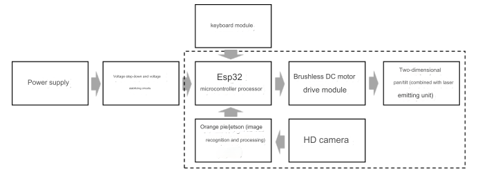
Figure 1 Overall Hardware Design Block Diagram of the System
The power supply uses a 11.3V power module, and through the step-down and voltage stabilization circuit, the generated voltage is supplied to the microcontroller processor, brushless DC motor drive module, brushless DC motor, and image processor respectively. The button module is directly connected to the microcontroller I/O, used to realize the reset of the laser, the rapid switching of different design functions, etc.; Orange Pi/Jetson is used to receive the image information of the high-definition camera, and through the image processing algorithm, to quickly recognize and judge the color and position of the laser, and transmit the recognition result to the microcontroller processor; the microcontroller processor then generates PWM signals with different duty cycles and outputs them to the brushless DC motor drive module, thereby driving the two-dimensional pan-tilt to quickly move, and finally realizing all the functions of the system.
Software System Design
A4 Target Paper Position Recognition
Since the outer frame of the A4 target paper is stuck with black tape, which has a large color contrast with the white background plate, it is relatively easy to extract the pixel coordinates of the four corners of the inner and outer rectangular frames of the black tape of the A4 target paper using the image segmentation function built into OpenCV. Since the obtained pixel coordinates cannot be better matched one by one, the black tape center path is fitted through an independently designed rectangular fitting algorithm. The specific method is to record the pixel coordinates of the inner and outer rectangles in the following form:
Determine the corresponding corner coordinates of the inner and outer sides at the same position through the distance calculation between two points, the calculation formula is as follows:
According to the arrangement result of the four corner points of the inner and outer rectangles, calculate the rectangular corner coordinates of the black tape center path, and draw a complete rectangular path through the straight line connection between pixels, and traverse all pixel coordinates on the rectangular frame in reverse, providing a complete running path for the lower machine, the algorithm flow block diagram is shown in Figure 2.
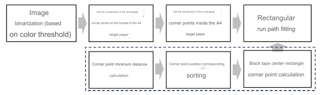
Figure 2 A4 Target Paper Position Recognition Algorithm
Laser Tracking
The laser tracking function of this design is mainly realized through the image recognition algorithm. After the high-definition camera captures the real-time video, the real-time video is sampled to obtain image data at adjacent times. In order to better recognize different laser colors, the extracted image frames are first converted from the RGB color space to the HSV color space, and Gaussian blur and median filtering are applied to reduce image noise and smooth image edges. Then, morphological operations (closing, opening, and dilation) are used to further remove noise and increase the contrast of the image for lasers and the background. Finally, the image is converted into a binary image through thresholding, and the contours that meet a certain area range are found, and the centroid of the laser is calculated, the processing flow is shown in Figure 3.
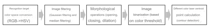
Figure 3 Laser Tracking Algorithm
Test Plan and Test Result Analysis
Test Method
According to the test indicator requirements of the selected topic, test the distance between the center of the spot and the origin, the distance between the center of the spot and the edge, the distance the spot deviates from the tape, and the distance between the centers of the two spots in the basic requirements part and the advanced part, all tests are repeated 9 times and the error results are manually measured.
Test Results
The basic requirements test and advanced part test are as follows:
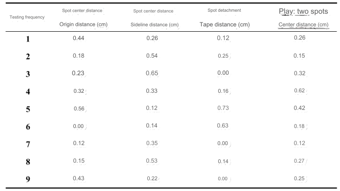
Basic Requirements Test and Advanced Part Test
According to the results of multiple actual tests, the designed system has good test effects both in the basic test part and the advanced part, and the generated test errors are within the acceptable range, the system has good real-time test accuracy.
Existing Problems
It should be noted that due to the use of the pause button test, there is a certain time difference between the real-time performance of the test results and the actual running effect, so the results obtained may be slightly less than the actual test. Due to the limited development time, the control of the motors in this system only adopts angle closed-loop control and does not add speed closed-loop control. Therefore, the control accuracy of the angle is significantly higher than that of the speed. In addition, the Orange Pi and Jetson used in this design have high costs, and subsequent improvements will consider low-cost solutions.
Conclusion
This design of the moving target control and automatic tracking system uses the ESP32-S3 microcontroller as the control core of the entire system, through the external high-definition camera as the image acquisition equipment, using Orange Pi/Jetson for real-time image processing, and independently designing the target paper center running path fitting algorithm, which can more accurately achieve the main functions of the selected topic. Due to the limited development time, the control of the motors in this system only adopts angle closed-loop control and does not add speed closed-loop control, subsequent optimizations will focus on considering low-cost dual closed-loop control solutions, thereby improving the system's construction cost and running accuracy.