Project Requirements
Task
Design a car following driving system using TI's MCU, consisting of a leading car and a following car. The cars must have line-following functionality with adjustable speeds between 0.3 ~ 1m/s and be able to complete driving operations on a specified path. The path of the driving area is shown in Figure 1. Point A on the path is the starting and ending point for each trip of the leading car. When the cars complete a trip and reach the end, both the leading and following cars must emit an audible alert. The leading and following cars can either travel along the rounded rectangular path ABFDE (referred to as the inner loop) or the rounded rectangular path ABCDE (referred to as the outer loop). When traveling on the inner loop BFD segment, the cars must emit a light indication. Additionally, during testing, a "stop and wait" indicator can be placed at a designated location on the straight section where point E is located (see the left side of Figure 1), instructing the leading car to stop at this point, wait for 5 seconds, and then continue driving.
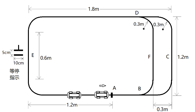
Figure 1 Schematic Diagram of the Car Following Driving Area
Requirements
- Place the leading car at the starting position A and the following car 20cm behind it. Set the leading car's speed to 0.3m/s and drive it along the outer loop path for one lap and stop. Requirements:
- The average speed error of the leading car should not exceed 10%;
- The following car must follow the leading car without collision;
- After completing one lap, the leading car stops at point A, and the following car should stop promptly with a time difference of no more than 1s and a distance of 20cm from the leading car, with an error not exceeding 6cm.
- Place the leading car at the starting position A and the following car at a designated location on the straight section where point E is located. Set the leading car's speed to 0.5m/s and drive it along the outer loop path for two laps and stop. Requirements:
- The average speed error of the leading car should not exceed 10%;
- The following car must quickly catch up with the leading car and then follow it at a distance of 20cm without collision;
- After completing two laps, the leading car stops at point A, and the following car should stop promptly with a time difference of no more than 1s and a distance of 20cm from the leading car, with an error not exceeding 6cm.
- Place the leading car at the starting position A and the following car 20cm behind it. The leading and following cars complete three laps continuously. The first lap, both cars travel along the outer loop path. The second lap, the leading car travels along the outer loop path, and the following car travels along the inner loop path, achieving overtaking. The third lap, the following car travels along the outer loop path, and the leading car travels along the inner loop path, achieving a counter-overtake and leading again. Requirements:
- Both cars must travel smoothly, successfully complete two overtakes without collision;
- After completing three laps, the leading car stops at point A, and the following car should stop promptly with a time difference of no more than 1s and a distance of 20cm from the leading car, with an error not exceeding 6cm;
- The car speed can be set autonomously but must not be lower than 0.3m/s, and the time required to complete the specified three-lap trajectory should be as short as possible.
- Place a "stop and wait" indicator at a designated location on the straight section where point E is located. Then, place the leading car at the starting position A and the following car 20cm behind it. Set the leading car's speed to 1m/s and drive it along the outer loop path for one lap without collision. Requirements:
- The average speed error of the leading car should not exceed 10%;
- The leading car must stop at the "stop and wait" point accurately with an error not exceeding 5cm;
- The stop time at the "stop and wait" point should be 5s with an error not exceeding 1s.
Instructions
- The size of the cars in the project should not exceed 15cm (width) X 25cm (length). The size includes the car body and the overall size of the sensors installed on the car.
- The driving area is covered with white paper, and the driving path is marked with 1cm wide black guide lines, which can be printed or printed on the white paper or directly pasted with black tape on the white paper. The starting point A on the track is marked with a black marker line perpendicular to the path guide line, which is 2cm wide and 5cm long. The "stop and wait" indicator is marked with two 2cm wide, 10cm long black parallel marker lines spaced 5cm apart. It can be pre-printed on a small piece of paper and then glued to the driving path guide line during testing. Except for the markings required by the topic, there should be no other indicator marks on the driving area.
- The driving of the following car is completely controlled by the leading car. The leading car has a start button and a setting button, while the following car only has an on/off switch and no other start or operation buttons. Each time the cars are placed at the specified positions on the driving path, the following car is powered on and in a state of waiting to receive instructions from the leading car. The leading car starts driving with one button press until the entire driving process is completed.
- During the two-car following driving process, in addition to the mutual communication between the two cars, there should be no external remote control or other communication instructions.
- In requirement 4, when the leading car encounters the "stop and wait" indicator, it must stop immediately. After stopping, the car body should be within the second horizontal line of the "stop and wait" indicator, and the distance the car head exceeds the second horizontal line is the parking position error.
Implementation Plan
The main control system of the two three-wheeled, two-wheel drive cars in this system uses TI MSP432. Through UWB positioning modules, HC-12 Bluetooth modules, tb6612 motor drive modules, grayscale sensors, and encoders, and by using a multi-sensor fusion algorithm to calculate the parameters needed for the controller model to give controllable PWM, the motion control of the cars is ultimately achieved. Meanwhile, to facilitate debugging of controller parameters, we use an OLED display to effectively monitor adjustments to relevant parameters. Finally, the two cars can follow the line at a certain speed and rely on external sensors to complete corresponding tasks. After repeated testing and improvement, the line-following car system is reliable, driving stably, and meets the index requirements.
Scheme Demonstration
Selection of Main Control Chip
The first consideration for selecting the car system architecture is the performance of the MCU, with the system clock being the most important factor, which directly affects the operation speed of the MCU. The car involves many sensor data and complex algorithms that need to be processed. If the MCU's performance cannot support such calculations, the entire system will not be able to achieve its various functions, leading to a collapse of the car system.
The MCU's IO ports are also important, with data from various sensors transmitted to the corresponding positions via IO ports, such as the number of USART, I2C, SPI, and GPIO.
Based on the above requirements, we discussed several different expected solutions as follows:
Option 1: Use msp430, this MCU has a high-performance, low-power 6xx series flagship model, reaching 25MIPS@3.3V, equipped with an innovative power management module and USB controller, equipped with an LCD controller, with 256KB FLASH, 18KB RAM, 74Pin, and the same power consumption as the 5xx series, but also integrates a voltage management module. However, the main frequency of this MCU is still too low.
Option 2: Use msp432 MCU, this controller has a high-speed 48MHZ clock, stable frequency controllability, combined with our expected sensor fusion solution for specialized design. And it can provide more IO ports and onboard peripherals, giving our multi-sensor fusion algorithm an effective implementation platform, but also bringing certain difficulties to our design and implementation.
After the above discussion, we chose option 2 that meets our needs.
Selection of Voltage Regulator Module
Option 1: Use linear components LM7805 three-terminal voltage regulator to form a voltage regulator circuit to provide voltage for the microcontroller. It has a small output ripple but is inefficient and prone to heat.
Option 2: Use components LM2596 to form a voltage regulator circuit, which is efficient and not prone to heat, but has a larger output ripple.
Considering the system performance, the car runs independently on batteries and requires efficient voltage regulation, while being less affected by output ripple, so option 2 is chosen.
Selection of Car Motor
Option 1: Use 310 motor, which has strong power but is heavy.
Option 2: Use ng20 reduction motor, which has slightly weaker power but is lighter.
After repeated research, considering maintaining speed while maintaining posture, the 310 motor with faster speed and larger torque was ultimately chosen.
Selection of Drive Module
Option 1: Use MOSFET and full bridge/half bridge drive chip to build motor drive, which allows large motor current to pass, but the structure is complex and the volume is large.
Option 2: Use drive module based on TB6612 chip, which is simple to use, convenient for wiring, and relatively small in volume, but the current that can be passed is small.
After comprehensive consideration, the car's volume should not be too large, and after testing, the drive current of the TB6612 module can meet the system requirements, so option 2 is chosen.
Theoretical Analysis and Calculation
Design of Car Motion Control
- A controller that controls by proportional, integral, and derivative of the deviation is called a PID controller. PID control solves the most basic problem that automatic control theory needs to solve, which is the accuracy, stability, and real-time performance of the system. According to the situation of path recognition, the car is controlled accordingly to achieve the purpose of setting the speed reasonably. The system adjusts the DC motor's speed by using the PID algorithm based on the speed value received from the speed detection module, thereby controlling the car's acceleration, deceleration, and steering.
Our group uses the incremental PID algorithm. Incremental PID control is a control algorithm that performs PID control on the increment of the control amount (the difference between the current control amount and the last control amount). Its basic formula is:
Where is the nth output increment, is the nth deviation, and correspond to the coefficients of proportional, integral, and derivative, respectively.
- Turning Control Method
The car's turning adopts differential speed control method, that is, by setting different inner wheel and outer wheel speeds to change the car's running direction. During the car's forward motion, the trajectory change detected by the infrared sensor is used as the turning condition. Based on the measured current car speed, the speeds of the inner wheel and outer wheel are adjusted separately. The inner wheel speed minus a certain percentage of the current speed, the outer wheel plus a certain percentage of the current speed, to achieve the purpose of differential speed control steering, making the car follow the track.
- Grayscale Sensor Calculation Position Method
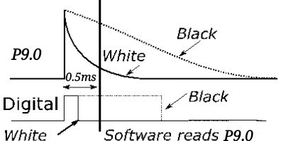
Figure 1 Basic Control Principle of Grayscale Sensor
This system uses grayscale sensors to detect the ground track. When the emitted infrared light hits a black target, it is reflected back, and the received feedback signal quickly becomes high. We read the data from the equally spaced infrared sensor array and assign each infrared sensor element with corresponding positional information. Since the sensor is close to the ground, it only outputs "1" when it detects a black thick line below. We multiply the positional information and the sensor feedback data bit by bit to obtain the relative positional information of the car from the track.
Analysis of Car Communication Mode
This system uses the HC-12 wireless module for communication between the two cars, operating in the frequency band of 433.4MHz to 473.0MHz, with 100 channels and a step of 40KHz.
Distance Control of Cars
This system's distance control uses Ultra-Wideband (UWB) positioning technology, which utilizes anchor nodes and bridge nodes pre-arranged on the front car, and communicates with the blind nodes on the rear car, positioning by measuring the transmission time delay difference between different base stations and the mobile terminal. The data returned by UWB is used to organize the speeds of the two cars, package the data into the PID, and control the speeds of the two cars through the PWM returned by the PID, thereby controlling the distance between the cars.
Circuit and Program Design
System Composition and Block Diagram
The overall block diagram of this system is shown in Figure 2. The processing MCU is MSP432, and the peripheral circuits mainly consist of grayscale sensors, drive modules, voltage regulator modules, and speed detection modules. The following diagram analyzes the composition of each module design.
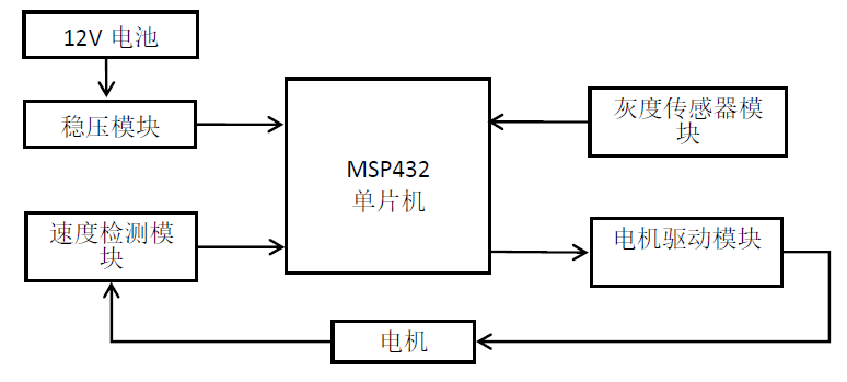
Figure 2 Overall Block Diagram of the System
Car Tracking Circuit
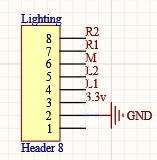
Figure 3 Car Tracking Circuit
Car-to-Car Communication Circuit
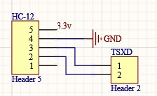
Figure 4 Car-to-Car Communication Circuit
Car Anti-Collision Circuit
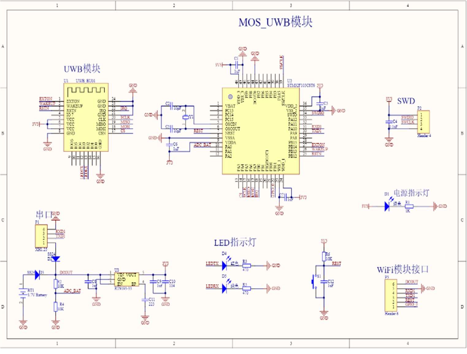
Figure 5 Car Anti-Collision Circuit
Program Overall Flowchart
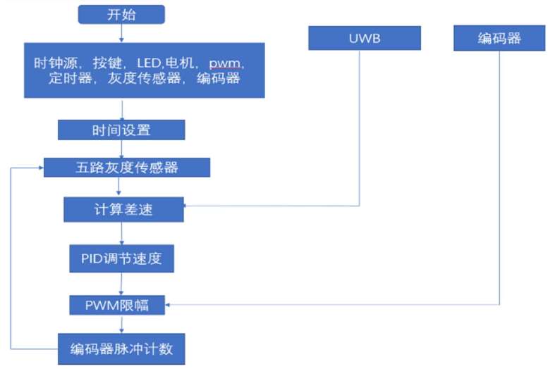
Figure 6 Program Overall Flowchart
Test Plan and Test Results
Test Methods and Instruments
Instruments: Oscilloscope (DSOX2012A), DC regulated power supply (GPS-3303C), Multimeter (DT9205A)
Test Method: Test method is first part then whole: First test each module circuit separately to ensure that it can achieve the function, then assemble the car, burn the program; then test the car as a whole. Place the car on the track, first test whether the car's tracking function is complete, then test whether the distance measurement function of the dual-car system is good, separately test the speed of the car and the distance error when the two cars stop. Continuously set the car's speed, repeat the above operation.
| Test Number | Target Time/s | Actual Time/s | Stopping Distance Error/cm |
|---|---|---|---|
| 1 | 18 | 16 | 2.6 |
| 2 | 18 | 17 | 1.0 |
| 3 | 18 | 18.6 | 0.6 |
| Test Number | Target Distance/cm | Target Time/s | Actual Time/s | Stopping Point Error/cm |
|---|---|---|---|---|
| 1 | 20 | 24 | 20 | 1.3 |
| 2 | 20 | 24 | 16.1 | 1.6 |
| 3 | 20 | 24 | 19.3 | 2.6 |
| 4 | 20 | 24 | 22 | 1.0 |
| 5 | 20 | 24 | 23 | 0.6 |
| 6 | 20 | 24 | 24.3 | 0.6 |
Result Analysis
Each part of the hardware circuit tested normally, able to achieve their respective functions. The code is written correctly without error, able to achieve the expected function, the car can achieve tracking and tracking function, and reach the designated position to stop, the buzzer sounds, the speed can also reach the specified requirements. The system basically achieves the requirements of the topic, the car travels smoothly, the performance is good. But there is a bit of a stutter at some corners, so further optimization is needed in the program and hardware performance.