Project Tasks and Requirements
Task
Design and produce a non-contact automatic measurement device for object shape and size. The layout of the device is shown in Figure 1. The measurement device is placed in the designated measurement area, and the target to be measured is placed in the target placement area. The device can measure the shape, size, and distance between the center point of the measurement head and the target, and use a laser beam to indicate the center position of the target. The background board is placed vertically 5cm behind the target, as shown in Figure 2.
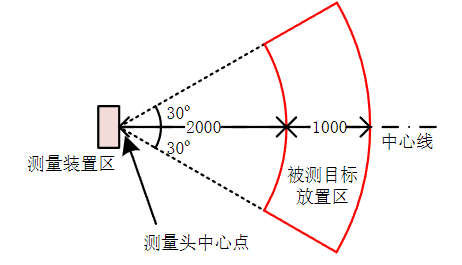
Figure 1: Test Scene Layout Diagram
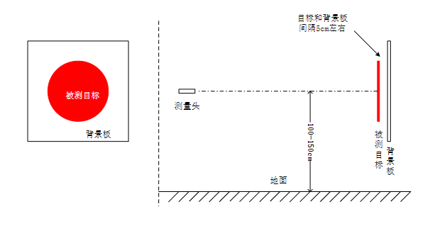
Figure 2: Target Board and Background Board Placement Diagram
Requirements
Select a planar target of a regular shape and place it on the centerline of the target placement area. Press the measurement button to start the measurement. After completion, display the target's side length (or diameter if the target is circular), geometric shape, and distance from the measurement head on the device. The entire measurement and indication process must not exceed 2 minutes.
Replace the target board, place the target and background board on the centerline of the placement area, and display the distance, shape, and size (side length). The measurement time must not exceed 2 minutes.
Automatic target search and measurement: The measurement head is aligned with the centerline (0º), and the target is placed in the target placement area at any selected position. After pressing the test button, the device automatically searches for the target, measures and displays the distance, shape, size, and uses a laser pointer to indicate the geometric center. The time must not exceed 3 minutes, the shorter the better.
Three-dimensional target measurement: Randomly select one from basketball, volleyball, and football, repeat the measurement three times, determine the type of ball, and measure the closest distance to the ball surface. The time must not exceed 2 minutes.
Implementation Plan
This non-contact automatic measurement device for object shape and size is designed with the ESP32-S3 microcontroller as the control core of the entire system, supplemented by related peripheral circuits. It can automatically measure the shape, size, and distance between the center point of the measurement head and the target, and use a laser beam to indicate the center position of the target. The system consists of buttons, motor drive module, motor, communication module, OLED display, power module, and recognition module. In the hardware circuit, a camera is used to identify the shape, size, and distance parameters of the target, the ESP32-S3 microcontroller detects real-time data, and displays the target's side length (or diameter if the target is circular), geometric shape, and distance from the measurement head on the display. In the software aspect, C++ programming and python3.6 are used to implement the measurement of the target's side length, geometric shape, and distance from the measurement head through the microcontroller program.
Scheme Demonstration
Voltage Reduction Selection
Option 1: Use Linear Regulator Power Supply (LDO). The outstanding advantages of low dropout linear regulators are the lowest cost, lowest noise, and lowest quiescent current. Its peripheral devices are also very few, usually only one or two bypass capacitors. However, the efficiency of linear power supplies is low, and the heat generation is large, requiring a larger heat dissipation area, and is only suitable for low dropout conversion and some occasions requiring a stable power supply voltage, such as supplying power to microcontrollers and other devices.
Option 2: Use Switching Power Supply. DC-DC includes boost (step-up), buck (step-down), Boost/buck (step-up/step-down), and inverting structures, with high efficiency, high output current, and low quiescent current. Compared to LDO, the power switch is small in size and suitable for high dropout conversion. Therefore, the switching power supply is used in this system.
Image Processing Module
Option 1: Use OpenMv. OpenMV is an open-source module focused on machine vision, based on the CPython programming language, providing rich image processing and computer vision functions. OpenMv has functions such as face recognition, photo taking, and video recording, but it cannot handle complex algorithms and cannot run for too long.
Option 2: Use K210. The K210 chip can be used for various embedded artificial intelligence applications, capable of real-time image processing, object detection, face recognition, voice recognition, and natural language processing. The main advantages of the K210 chip are low power consumption and small size, but it is slightly inferior in computational power and graphics processing capabilities.
Option 3: Use Jetson. The Jetson platform is based on NVIDIA's GPU architecture, providing rich software support and development tools, making it easier for developers to develop and optimize applications. Compared to OpenMv and K210, Jetson has stronger computational power and graphics processing capabilities, so Jetson is used in this system.
Motor Selection
Option 1: Use Servo Motor. A servo motor is a motor with position feedback, which can accurately control the motor angle. Servo motors are usually composed of a DC motor, a position sensor, and a control circuit, widely used in robotics, model aircraft, automation equipment, and other fields, capable of precise position control.
Option 2: Use Brushless Motor. A brushless motor controls the rotor position through an electronic commutator. Brushless motors usually consist of a rotor and a stator, with permanent magnets on the rotor and coils on the stator being alternately energized through the electronic commutator to achieve motor rotation. It has the characteristics of high efficiency, high torque, and high speed. Overall, servo motors are more suitable for precise position control, while brushless motors are more suitable for applications requiring high efficiency, high torque, and high speed. Therefore, brushless motors are used in this system.
Motor Control Selection
Option 1: Use Six-Step Phase Change. Six-step phase change is a simple motor control method that controls the rotation of the motor by sequentially switching the three phases of the motor, suitable for some simple motor control applications.
Option 2: Use SVPWM. SVPWM is an advanced motor control method that controls the motor's speed and torque by adjusting the motor's voltage and frequency, with high control accuracy and efficiency, suitable for applications with high requirements for motor control performance. Therefore, SVPWM is used in this system to control the motor.
System Design and Implementation
The overall composition block diagram of the system is shown in Figure 1.
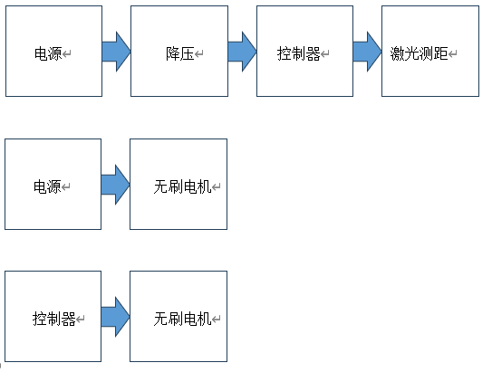
Figure 1
Voltage Reduction Circuit Design
Using a switching power supply for voltage reduction is a common power conversion method that can convert high voltage to low voltage to supply power to the load. The step-down switching power supply usually includes an input filter circuit, a switch tube, a transformer, a rectifier circuit, an output filter circuit, and a feedback control circuit. The basic working principle of the step-down switching power supply is to switch the input voltage into a high-frequency pulse signal through the switching action of the switch tube, and then convert it into a stable low-voltage output through the transformer and rectifier circuit, thus converting the 12V power supply to 5V.
Brushless Motor Control Design
First, connect the motor, connect the power and control signal lines of the brushless motor to the corresponding pins of the ESP32. Then configure the GPIO pin working mode and level in the ESP32 code, use SVPWM to achieve brushless motor control, and finally control the motor's rotation through the functions provided by the motor control library.
Laser Rangefinder Design
Laser ranging is a method of distance measurement using laser technology. It calculates the distance by emitting a laser pulse and measuring the time from emission to reception of the laser pulse. Laser rangefinders usually consist of a laser emitter, a receiver, a clock, and a calculator. The laser emitter emits a laser pulse, the receiver receives the reflected laser pulse and converts the received signal into an electrical signal. The clock is used to measure the time of the laser pulse, and the calculator is used to calculate the distance.
Image Processing Algorithm Design
Use template matching and circular Hough transform, as well as their combination, to achieve judgment and recognition of circles, rectangles, and triangles. The circular Hough transform is used to detect circles in the image. The circular Hough transform searches for parameters in the parameter space of circles and lines in the image to find parameters that match the circles and lines in the input image. In the OpenCV library, the HoughCircles function can be used to implement the circular Hough transform algorithm. Template matching and circular Hough transform are combined to detect triangles and rectangles. First, template matching can be used to detect and recognize the edges of triangles and rectangles in the image. Then, the circular Hough transform can be used to detect and recognize circles and lines in the image, further determining the position and shape of triangles and rectangles.
Communication Module Design
Communication using WiFi through the TCP protocol is a common network communication method. The TCP protocol is a reliable transmission protocol that can ensure the reliable transmission of data, ensuring that data is not lost or damaged. Using WiFi as the communication medium can provide high-speed data transmission rates and stable connection quality. Using JSON data formatting to transmit data can facilitate data parsing. JSON is a lightweight data exchange format with good readability and scalability, which can facilitate data parsing and processing. In network communication, using JSON to format data can reduce the size of data transmission and improve the efficiency of data transmission.
Test Plan and Analysis of Test Results
Test Instruments
Oscilloscope, voltmeter, adjustable power supply, digital generator, tape measure.
Test Methods
Distance Test
Use monocular camera ranging. In the figure, f is the focal length of the camera, and c is the optical center of the lens. The light emitted by the object passes through the optical center of the camera and then forms an image on the image sensor or, in other words, on the image plane. If the distance between the object plane and the camera plane is d, the actual height of the object is H, and the height on the sensor is h, H must be known to obtain the distance d. The relationship between them is obtained from the similarity of triangles: d/H=f/h. The principle diagram of monocular camera ranging is shown in Figure 2.

Figure 2
Circuit Test
When testing the circuit, use an oscilloscope to observe and analyze the signal waveforms in the circuit, displaying the waveform diagram of voltage and current over time, helping us understand the working state and performance of the circuit. Use a voltmeter to measure the voltage in the circuit. Use an adjustable power supply to provide adjustable voltage and current, as adjustable power supplies usually have adjustable output voltage and current limits and have overload and short circuit protection functions, so they can be used to test and power various components and devices in the circuit. Use a digital generator to generate adjustable signals. Digital generators usually have multiple output channels and adjustable output parameters, which can be used to test and debug various signal sources and signal processors in the circuit.
Test Results
Under the condition that all indicators of the designed automatic measurement device meet the requirements, multiple tests were conducted on each requirement. Select a planar target of a regular shape and place it on the centerline of the target placement area. Press the measurement button to start the measurement, and the stopwatch starts timing simultaneously. After the measurement is completed, measure the actual value with a ruler, compare it with the measured value, observe the error value, and whether the measurement time exceeds the specified time. As shown in Figure 3.
| Measured Distance (mm) | Measured Side Length or Radius (mm) | Actual Side Length (mm) | |
|---|---|---|---|
| Rectangle | 2801 | 190/110 | 498/293 |
| 2753 | 193/110 | 408/293 | |
| Triangle | 2283 | 228/227/231 | 500/500/500 |
| 2513 | 219/208/208 | 500/500/500 | |
| Circle | 2301 | 112 | 250 |
| 2787 | 97 | 250 |
Error Reasons
The instruments used in the experiment may have inherent errors, possibly due to imperfect performance of the instruments, inaccurate calibration, or aging. Changes in the experimental environment may affect the experimental results. Errors may occur during the experiment, such as reading errors, inaccurate instrument placement, etc., which may be due to technical proficiency, non-standard operation, or negligence. Imperfections in the experimental design or inaccuracies in the assumptions may lead to errors. For example, ignoring some influencing factors, insufficient sample size, etc.
Conclusion
This system uses the ESP32 as the control core to design an automatic measurement device that can measure the shape, size, and distance between the center point of the measurement head and the target, and use a laser beam to indicate the center position of the target. This system has satisfactorily completed all the basic and advanced requirements of the topic, with overall good performance. However, due to time constraints, the geometric center indication using a laser pointer has not been well realized, and the system needs further improvement and refinement.